Space Charged AM
Broadcast and Short Wave Radios
(Winter 2016) Tracking Calc (Use Save As)
So before I tell you about the radios let me tell you about me and what I know and what I found out.
First I found out I did not know as much as I thought I did. I am not a radio engineer; I have been
into radio for over 60 years and am still learning. All self taught so there are many holes in what I know.
all of the words mean.
I will show you how I got my two radios to work, and work well.
I wanted 12 volt tubes for least amount of current draw.
I can build regens, TRF's and combinations or variances of each. Regenerative Receivers work very well
but take some constant knob turning.
or another made it more and more difficult. IF cans for one, one is not enough and I did not have two alike
or I liked that could be modified.
So to get started I made my own from scratch.
Well kind of, how do I hook it up? What happens if I reverse the leads? Some circuits have an IF with one coil
and some with two coils in the can. Testing parts out of the circuit and in the circuit, they act differently.
So I build single coil 1700 KC IF coil on slug tuned form and they seem OK.
and test each stage. I build test boards, ten of them.
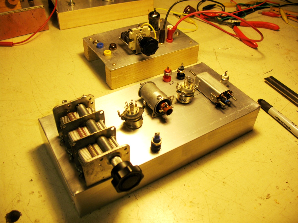
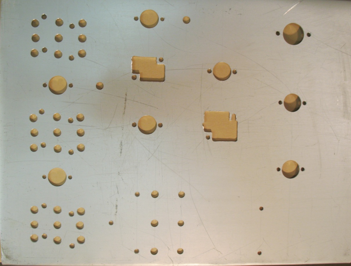
LO in the back and
Front End with parts placed
Then I start the Front end with the homemade 1700KC IF cans.
Above is Pictured A
Test Front End with 1700KC IF
These
numbers are for 1700KC IF, the finished radio used 429KC IF.
I build my first front end mixer with a 12AU6A, and an IF with 12BA6. Found a Double gang 7-413pF.
I want to tune from 510Kc to 1550 KC. Well with 200uF I need a cap that goes from 54pF to 460pF and
it should tune from 520-1561 close enough for front end, I think. Now how to make the cap 7-413pf be
52-469pF? I parallel the cap with a fixed cap of 47pF, That will give me 54-460pF. I wrap a coil on a PVC pipe,
1.82 in diameter and 1.625 long, I thread it 48PTI and wrap 78 turns on it, 200pF. I test it and it is good.
Coil form was PVC 1.060 diameter and .375 winding space for 38 turns of 31 gauge. Gave me 50 uH.
I added trim cap of 70 pf in parallel with the LO section of the tuning cap, and then series it with 130 trim
and some work so-so.
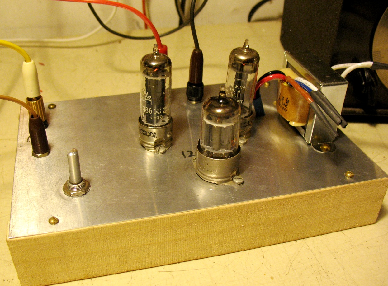
I broke down
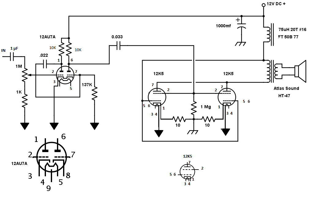
and bought a transformer, Atlas Sound HT-47 for $12.78
from "LowVoltageProducts.com". This amp works very well, with plenty of volume.
I hooked it up to a crystal set and the sound was so nice, no distortion.
from "LowVoltageProducts.com". This amp works very well, with plenty of volume.
I hooked it up to a crystal set and the sound was so nice, no distortion.
The front end works with a TRX amp, the tube amp works with a Xtal set, but they do not work together.
Maybe not enough drive? Wrong. Maybe impedance is wrong? Wrong. I test, I change resistors.
I change tubes. I change caps. Nothing gives me what I want. I build many variations with different
tubes and designs. Some work badly and some not at all.
Things got quite
confusing and I lost track of time and of exactly what I did each and
every day
for the next month. Really a month, I am old and retired and its winter and it is raining.
I will make this work! It should work. So I know that two days were spent trying to understand
what happened to the front end, it went into a hole and I could barely get anything out of it.
Then I noticed I had moved my antenna switch and had no antenna for two days. I moved the switch
and the radio came alive. I was mad to say the least.
I built about 40 individual test rigs. I made the chassis myself. I scrounged all the connectors and
made patch cords and built and tested and built and tested. Some worked but not like they should.
And I could not match up the IF with the Amp.
I spent
several days
on a detector test rig 12AV6, and it was dead from day one. I built the AVC circuit,
then I pulled it out. I needed to just make it detect and pass on the signal. Many 15 hour days later
I notice a cap that goes from the grid back to the diode through a resistor, and to the IF output,
I see I have none. I put in a cap and the tube comes to life. I must have built 4 or 5 different tube
detectors. Now this detector works.
I put the front end
and IF strip into the detector and the detector into the amp and no
luck.
Blurry old eyed vision, I failed to see that I have two caps in series, one on the output of the
detector and one on the input on the amp. I remove one.
Blurry old eyed vision, I failed to see that I have two caps in series, one on the output of the
detector and one on the input on the amp. I remove one.
I call my sister. My wife will not give me the correct response, after being usurped by a radio.
My sis says �that�s great�; she has no idea what I did, or what I have been through.
I don�t care I need someone to say it.
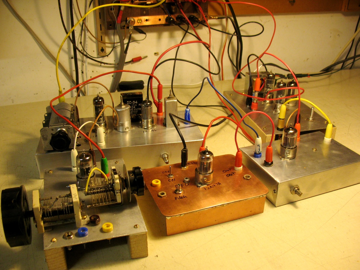
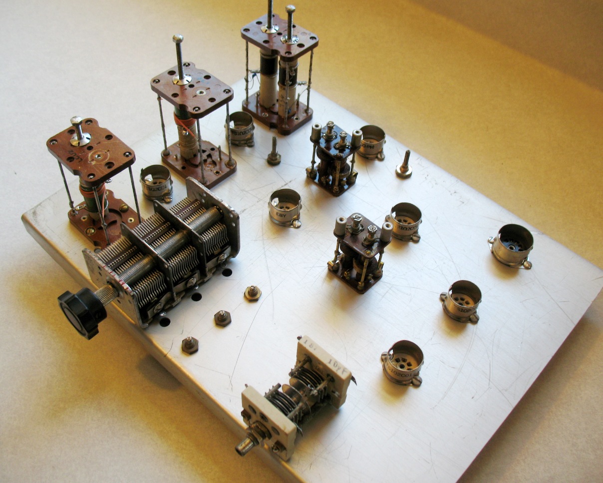
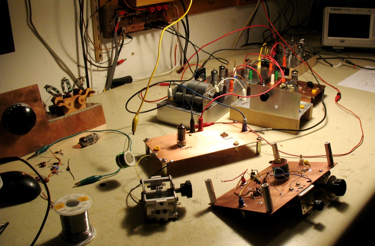
This was the SW test
version with the Front End in the back left and the audio amp back
right,
the LO
is left front and the BFO in the middle and detector front right. It worked but not as good as I thought it should.
More testing tried an RF amp up front with some success. Still not happy.
More testing of
different LO
OK enough of
that.
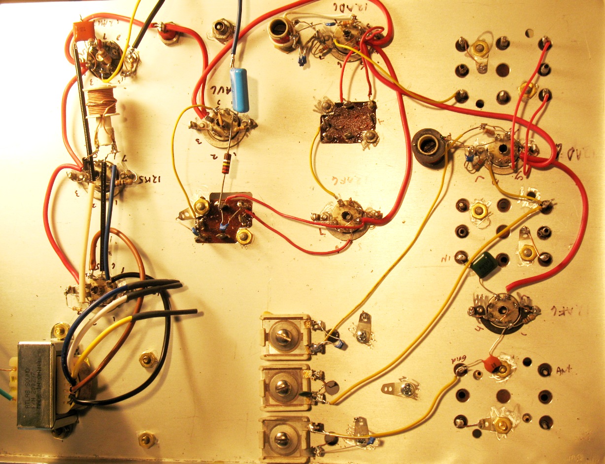
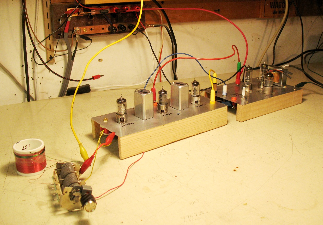
This is the version I ended up with one for Broadcast and one for Short Wave.
This is the version I ended up with one for Broadcast and one for Short Wave.
I decide to
change back
to broadcast band and try new IF transformers.
I bought
tubes, I
bought IF cans, I bought an output transformer.
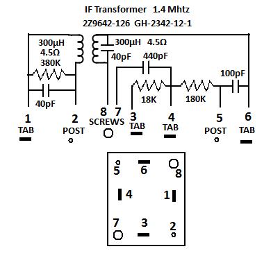
The IF cans I bought were 1.4 MHz. They had too much stuff on the inside so
I stripped them and made them 429 KC.
The IF cans I bought were 1.4 MHz. They had too much stuff on the inside so
I stripped them and made them 429 KC.
IF cans as I got them. $5.00 each from Surplus Sales of Nebraska � Item GH2342-12-1
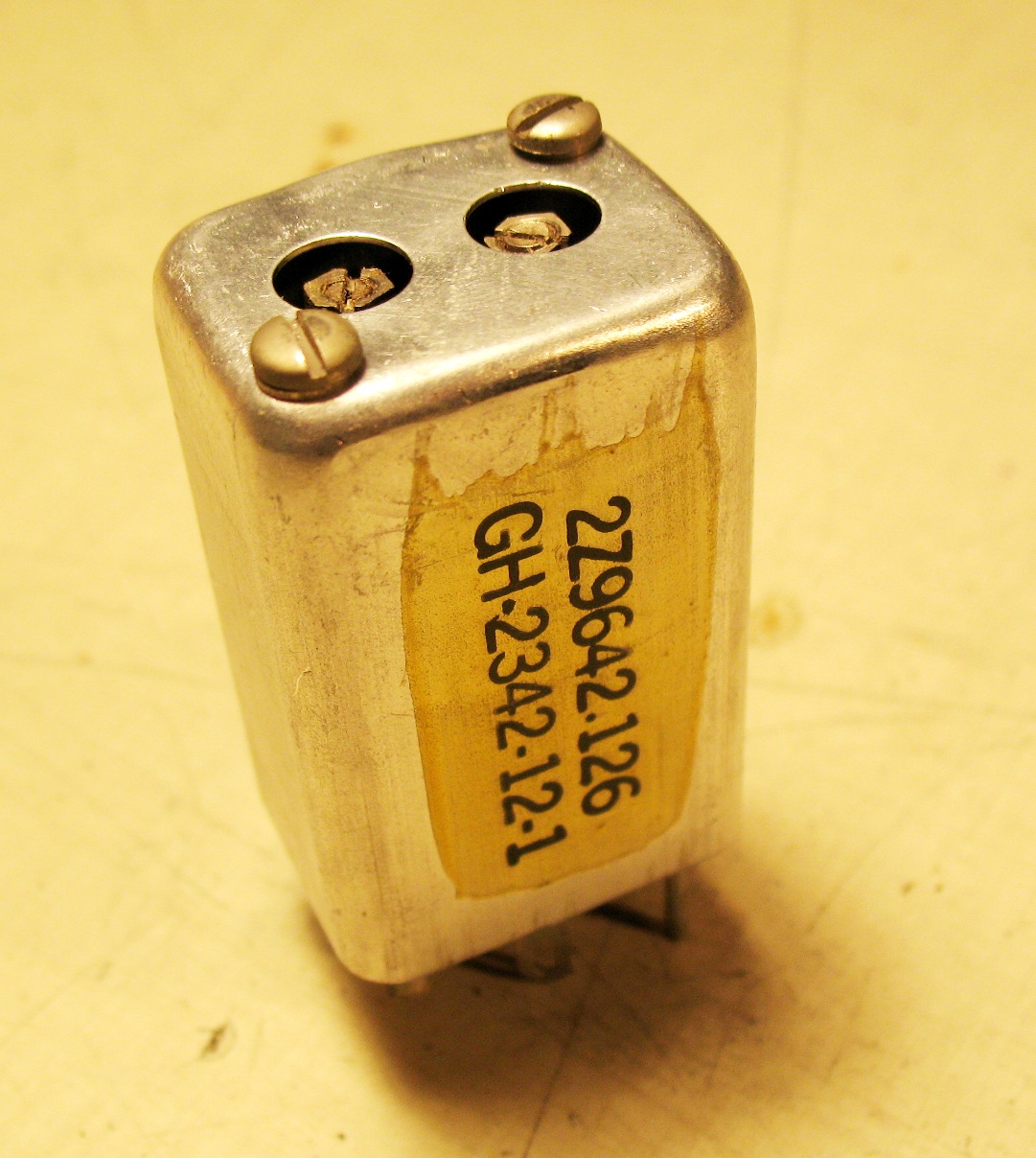
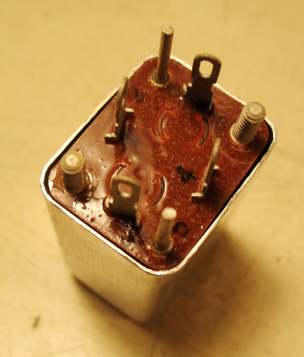
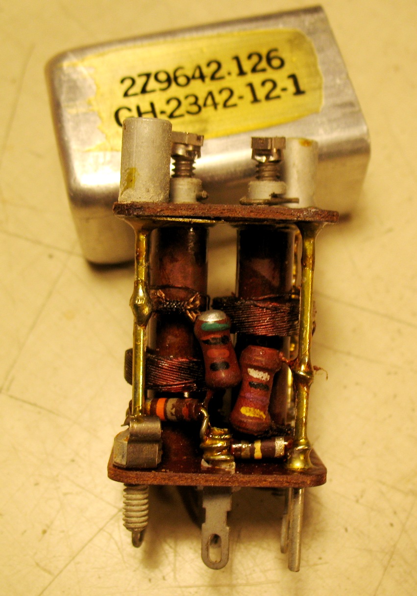
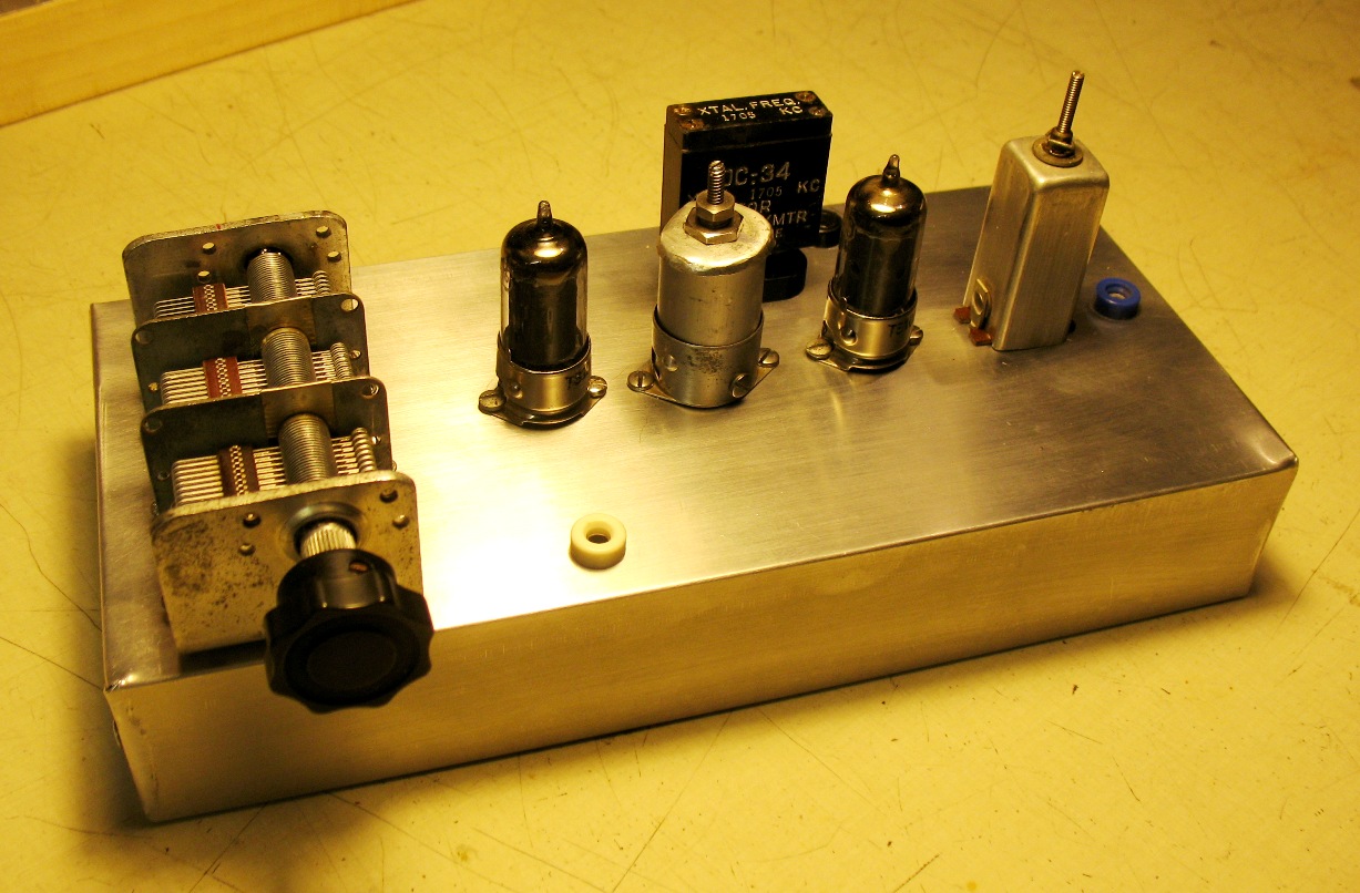
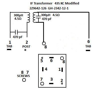
After I changed them:
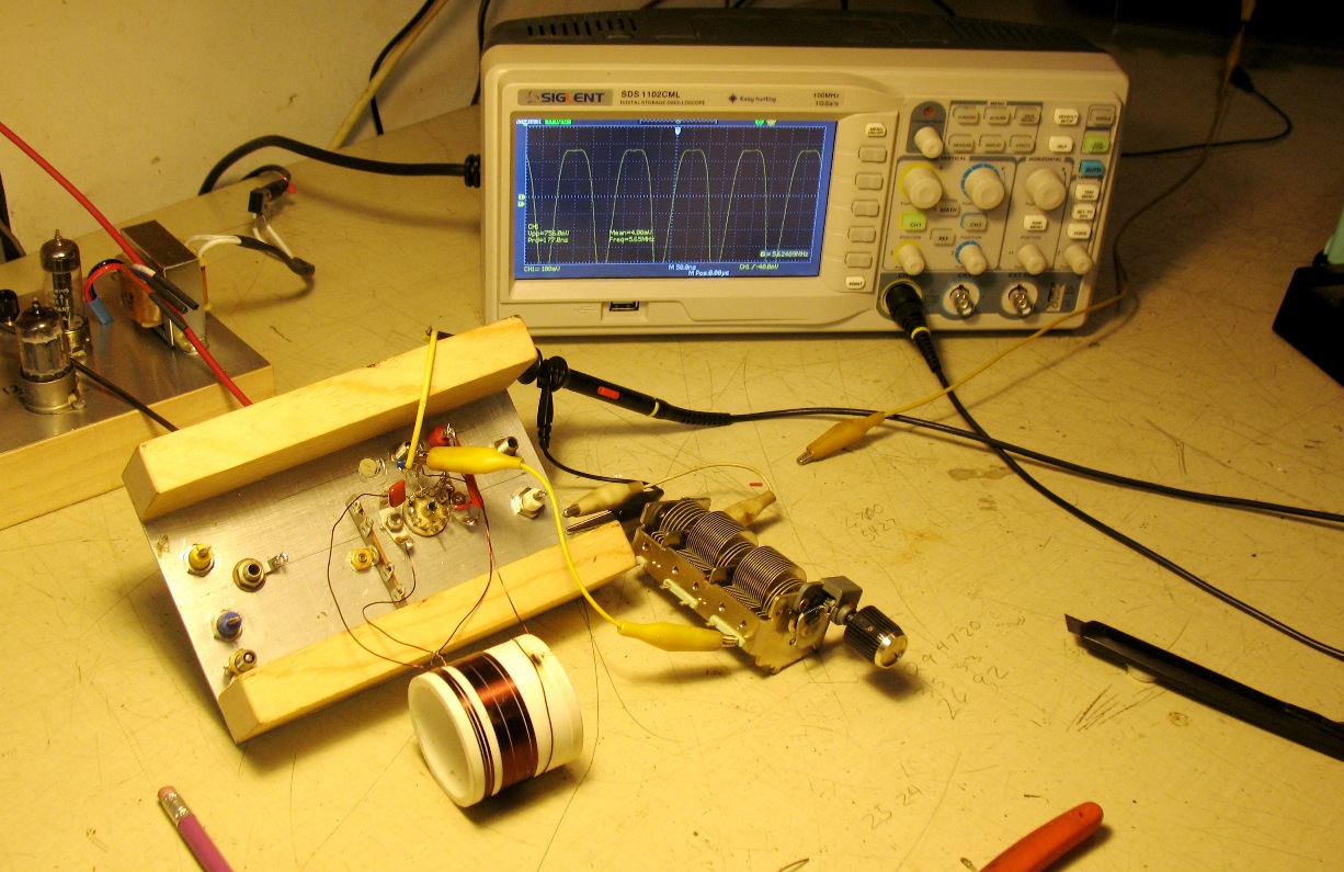
Testing front end coil.
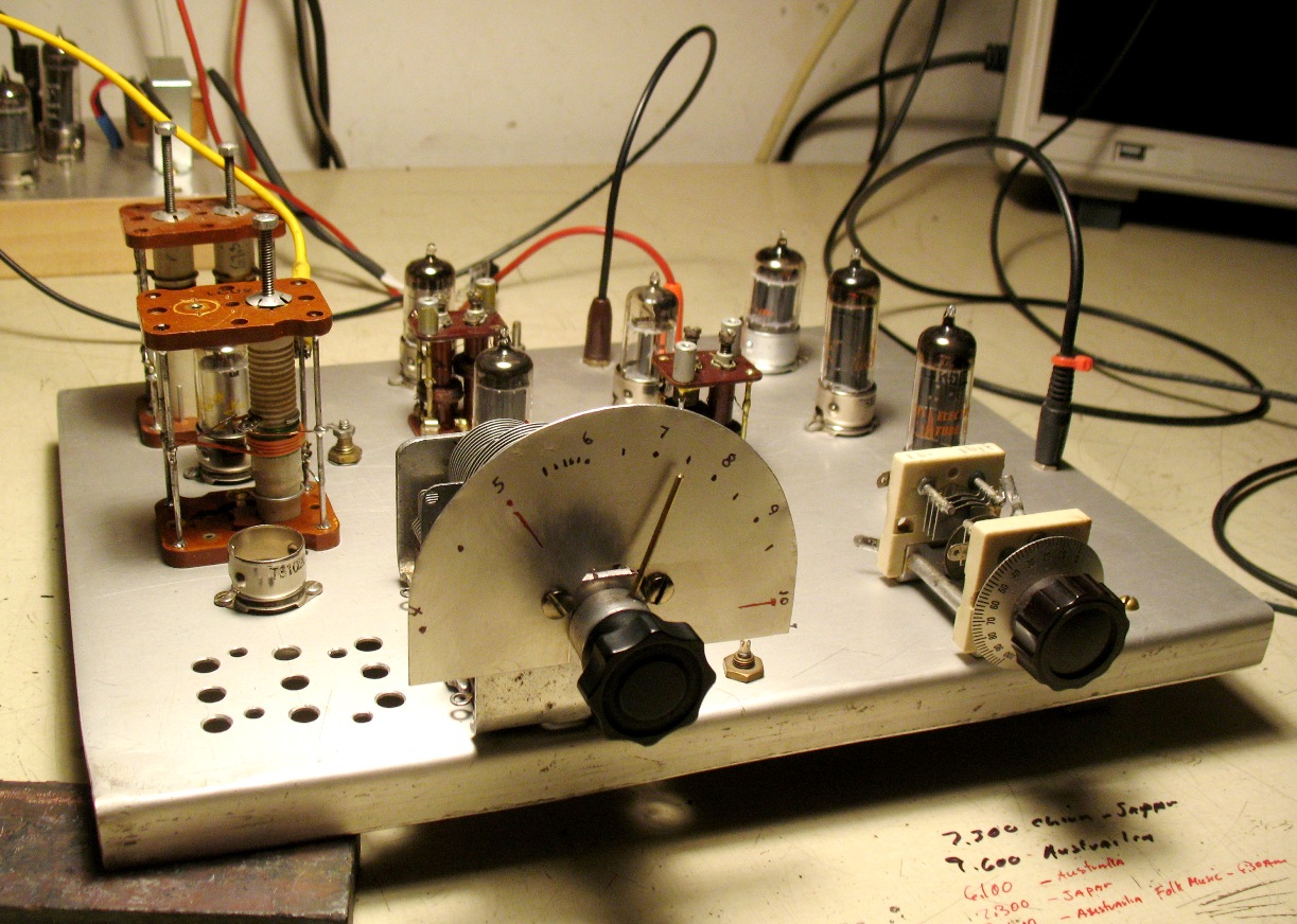
Finished AM Test Radio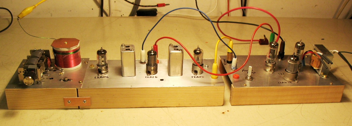
Finished AM Test Radio
This radio works good.
Things of note:
Use a tracking calculator to make the two capacitors track properly. It makes the trial
and error method obsolete. It also is right the first time. I wrote the tracking calcultor
using several sources of other's work. It is a gwbasic program that will run under DOS
the cmd prompt C:\ in a small window. The print utility will only work with a parallel
port.
Most of the parts found in a High Voltage Radio are not needed in low voltage radio.
Dropping resistors and most caps to ground just limit the radio and add to distortion.
The math on paper
and the real world are different. Wire length and posistoin of
parts
come into play.
You need to be able to adjust the coils and the caps in circuit to get things right.
come into play.
You need to be able to adjust the coils and the caps in circuit to get things right.
Close cap and
adjust
trim cap to low frequency wanted.
Do it several
times
to get the best balance.
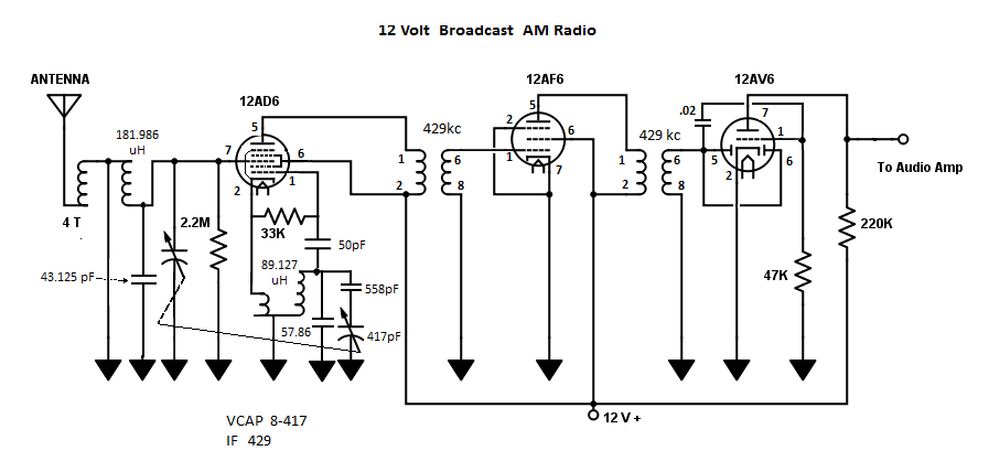
Coil Data for BC.
Front End Secondary
Coil (final coil)
Form .750
diameter
X 1.2 long winding space 181.986 uH, I put too much on and peeled
it off till it hit the range I needed.
it off till it hit the range I needed.
Primary is 8
turns
over the secondary.
Local Oscillator
Form .375
diameter
X 1.o long winding space, 89.127 uH same as above
I tried
electron coupled but would not keep running so I went to link coupled.
BC used Capacitor
from junk stereo
8pF to 417pF
Front end section needs to be 51pF � 460pF
Parallel 43pf will give
51pF � 460pF
LO section needs
to tune from 979 � 2079 KC
89.127 uH
C2 is
57.86
C3 is 558
C3 is 558
To change BC Radio to Short Wave change the front end coil and cap, change the LO coil and cap.
Add BFO at 1.5 KC low of IF, for CW and SSB.
I will document short wave soon.